Frequently Asked Question
FAQs for company
Please contact us at sale@aposunmeter.com directly, if below answers cannot help you
You can directly buy our products from our authorized online shopes or our marketing representative.
Some Aposun products have passed RoHS CE Certificate.
All Aposun products come with a manufacturer’s 12-month warranty. Please view more about product warranty.
We do international business for 10 years, you just take picture, video with specific description via mail, our tehcnical team will analize and support accordingly.
Also can support through whatsapp and telephone conference.
Accept payment via T/T (Bank transfer), Western Union, and PayPal.
3 working days for some in stock products,
5 working days for most of goods,
2 weeks for bulk order,
All goods will be tested for 24 hours before package.
3-5 days by express to your doorstep,
2-5 days by air to your nearest airport,
30 days by sea to your nearest seaport.
FAQs for product
- All
- FAQ for power meter
- FAQs for Universal panel meter
- FAQs for UV lamp & UV ballast
- FAQs for UV monitor
- FAQs for UV sensors
Why Does My UV Intensity Reading Decrease Over Time? Understanding UVC Intensity Instability and How to Fix It
If you’re using a UVC intensity monitor or sensor and have noticed that your UV intensity readings are decreasing over time, you’re not alone. Many people experience this issue, especially when working with UVC mercury lamps. But don’t worry, it’s usually not a problem with your sensor or monitor! Let’s explore why this happens and how you can manage and resolve it.
Visualizing UVC Intensity Changes Over Time
To help you understand the intensity fluctuations you may be seeing, here’s a chart that illustrates the typical behavior of UVC mercury lamps over time:
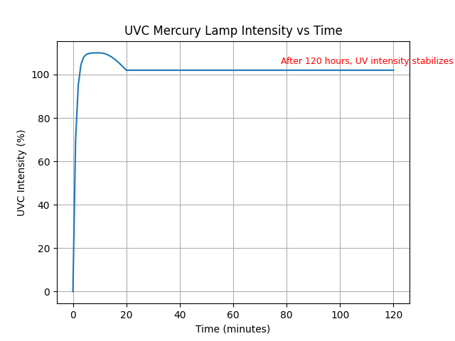
Figure 1: UVC Mercury Lamp Intensity vs Time. This graph shows how UVC intensity fluctuates when the lamp is first turned on and stabilizes after approximately 120 hours.
As shown in the chart, UVC intensity peaks in the first few minutes, stabilizes after 20 minutes, and reaches its final, steady intensity after 120 hours of continuous operation. This is a normal behavior for UVC lamps and is important to understand when monitoring UV intensity.
Understanding UVC Intensity Fluctuations: What’s Going On?
When a UVC mercury lamp is turned on, it doesn’t immediately deliver stable intensity. The UVC intensity fluctuates significantly in the first few hours due to the lamp’s warm-up process and natural degradation over time. Here’s what happens:
-
Initial Fluctuation (0-5 minutes): After turning on the UVC lamp, the intensity peaks within the first 3-5 minutes. During this time, it’s normal for the intensity to be unstable.
-
Stabilization (20 minutes): Within 20 minutes, the UVC intensity will start to stabilize as the lamp warms up and reaches a more consistent output.
-
Final Stability (120 hours): After around 120 hours of continuous operation, the UVC intensity will reach its final, stable output.
Common Causes of UV Intensity Decrease: Why Does It Happen?
It’s important to note that UVC lamps naturally degrade over time. However, several other factors may contribute to significant drops in intensity. Here are the common reasons:
-
Incorrect 100% Intensity Setting Right After Startup: Setting the intensity to 100% immediately after turning on the UV lamp may result in inaccurate readings, as the lamp hasn’t had time to reach its peak intensity. It’s always a good idea to wait for the lamp to warm up (3-5 minutes) before setting the intensity.
-
Low-Quality UVC Mercury Lamp: Cheap or low-quality lamps may degrade faster and lose efficiency over time. This leads to a noticeable decrease in intensity. When choosing a UVC lamp, make sure to buy high-quality lamps to ensure long-lasting performance.
-
Environmental Factors (Temperature Fluctuations): Temperature plays a huge role in the stability of UVC intensity. If your system is operating in an environment with significant temperature fluctuations, this can cause the intensity to vary. Keep the temperature stable to avoid these problems. For instance, if the UV system is placed in an enclosed space where the temperature rises and falls rapidly, you may notice greater intensity changes.
How to Set Your UVC Intensity Sensor and Monitor for Stability
Now that we understand the causes, how can you minimize fluctuations and ensure your UVC system is performing optimally? Here are some tips:
-
Wait for the Lamp to Warm Up: After turning on the UV lamp, wait 3 to 5 minutes for it to stabilize before adjusting the intensity settings. This ensures you are setting the correct intensity level once the lamp has reached its peak.
-
Allow for Long-Term Stability (120 Hours): For the best results, it’s highly recommended to wait for 120 hours of continuous operation before making any further adjustments. This allows the lamp to reach its final stable intensity and minimizes fluctuations.
-
Set the Low-Intensity Alarm Appropriately: You can also configure your UVC intensity monitor or sensor with a low-intensity alarm, but make sure it’s set correctly based on the lamp’s warm-up time and final stable output. This will help you receive alerts if the intensity falls below the desired level.
How Long Do UVC Lamps Last, and Why Do They Lose Intensity Over Time?
UVC mercury lamps typically have a lifespan of 9999 hours. Over time, as the lamp ages, the UVC intensity naturally declines. This is due to several factors, including:
- Lamp degradation: As the lamp is used, its internal components wear down, leading to a decrease in intensity.
- Environmental factors: Poor environmental conditions (temperature, humidity) can accelerate degradation.
For example, after 195 hours of use (around 8 days), it’s not uncommon to notice a slight decrease in intensity, especially if the lamp is not of high quality or the environment is not ideal.
Is It Time to Replace Your UVC Lamp?
If you’ve been using your UVC lamp for a long period (e.g., over 9999 hours) or notice a significant decrease in intensity, it might be time to consider replacing it. Regularly replacing your UVC lamps based on their recommended lifespan ensures your system remains efficient and effective.
Should I Worry About These Fluctuations in My UV Disinfection System?
Generally, no, you don’t need to worry. These fluctuations are temporary and don’t affect the overall performance of your UV disinfection system. After the lamp stabilizes, you’ll get consistent intensity readings, and your system will continue to perform its disinfection tasks effectively.
To keep your UV system working optimally, follow these steps:
- Proper installation and maintenance are crucial.
- Regularly replace lamps according to their lifespan.
- Ensure optimal operating conditions (temperature and power stability).
Introducing the CHS4CM UVC Intensity Monitor with Automatic 100% Intensity Setting
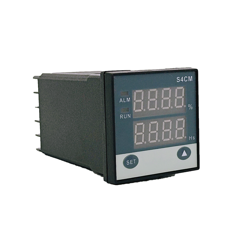
If you’re looking for a solution to minimize the impact of UVC intensity fluctuations and ensure your system stays stable, the CHS4CM UVC Intensity Monitor might be the answer.
This monitor comes with a built-in program that automatically adjusts the intensity setting to 100% 120 hours after lamp startup, helping to reduce instability and improve the overall accuracy of your intensity readings. This feature is especially useful for those who want to avoid manual adjustments and ensure reliable UVC monitoring over time.
Call to Action:
Need help setting up your UVC intensity sensor or monitor? Contact us for expert advice and support!
Best Position to Install a UV Intensity Sensor on UV Sterilizers or UV Cell
1. Can we install the UV intensity sensor at the end of the UV sterilizer (or UV cell)?
Yes, you can install the UV intensity sensor at the end, but we do not recommend it. Sensors installed at the end may only capture the UV light from lamps closest to them, leading to inaccurate readings. This can affect the effectiveness of your sterilization process.
2. Where is the best place to install the UV intensity sensor?
The best place to install the sensor is in the middle of the UV lamp flange or centrally within the UV chamber. This allows the sensor to measure UV light evenly from all the lamps, ensuring more accurate monitoring and optimal disinfection performance.
3. Why is installing the sensor at the end not ideal?
When the sensor is installed at the end of the UV cell, it may not capture the full UV output from all the lamps. The lamps closest to the sensor will dominate the readings, while those farther away won’t be measured accurately, leading to unreliable results.
4. Can you show us where the UV intensity sensor should be placed?
Yes! See the diagram below for the best placement of the sensor within the UV sterilizer:

How Temperature Affects UV Intensity Output
1. How does temperature affect UV output from UVC lamps?
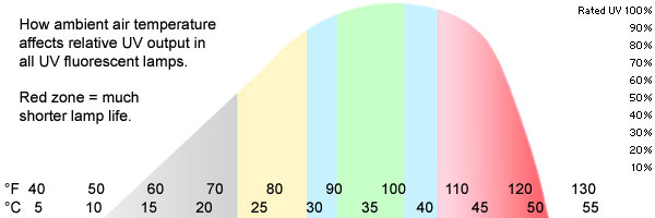
Temperature has a significant effect on UVC lamp performance, especially in disinfection systems. UVC lamps are highly sensitive to temperature changes, but you can’t visually gauge the UV output since the visible light is unrelated to the UV performance.
- Optimal Temperature: UVC lamps perform best in air temperatures between 90°F and 100°F (32°C to 38°C).
- High Temperature: If the air temperature exceeds 110°F (43°C), UV output dramatically drops, and the lamp’s lifespan shortens.
- Low Temperature: Below 90°F (32°C), UV output decreases moderately, and by 70°F (21°C), the output can be reduced by 50%.
2. Can I visually inspect the UV output?
No, you can’t assess UV output by simply looking at the lamp. The visible light is not a reliable indicator of UVC intensity. Instead, you should monitor the ambient air temperature around the lamp to get a good idea of its UV output.
3. What happens when the UVC lamp overheats?
At temperatures above 110°F (43°C), the mercury vapor pressure inside the lamp becomes too high, which drastically reduces UV output and shortens the lamp’s life. Overheating can quickly degrade the lamp’s performance and disinfection effectiveness.
4. What happens when the UVC lamp is too cold?
If the air around the UVC lamp drops below 90°F (32°C), the UV intensity gradually decreases. At 70°F (21°C), the UV output can be reduced by half, greatly diminishing its disinfection capabilities.
5. How can I ensure optimal UVC lamp performance?
Monitoring the air temperature around the lamp is essential. A UV intensity and temperature sensor ensures that the air temperature stays in the optimal range. Running the lamp at the correct temperature ensures effective disinfection and extends the life of the UVC lamp.
6. Why should I choose APOSUN’s UV Intensity Temperature Monitors?
At APOSUN, we offer advanced UV intensity temperature monitors to help maintain the ideal conditions for your UVC lamps.
- Real-Time Monitoring: Our monitors provide real-time data on UV output and temperature, ensuring optimal lamp performance.
- Temperature Alerts: They alert you when temperatures rise or fall outside the optimal range, so you can take immediate action.
- Improved Lamp Lifespan: With proper temperature control, you can extend your UVC lamp’s lifespan and maximize disinfection efficiency.
7. How does the APOSUN CHS9EM UV Intensity Monitor enhance performance?
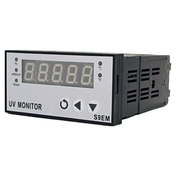
Our CHS9EM UV Intensity and Temperature Monitor offers precise readings of both UV intensity and ambient air temperature. The built-in alert system warns you when the temperature reaches levels that could reduce UV output, preventing performance degradation and system inefficiency.
8. Temperature vs. UV Output: A Visual Guide
The chart below shows the relationship between ambient air temperature and UV output. This illustrates why keeping the air temperature in the optimal range is critical for maintaining maximum UV output.
Key Takeaways:
- 90°F-100°F (32°C-38°C) is the optimal air temperature range for UVC lamp performance.
- Overheating and low temperatures can significantly reduce UV output and lamp lifespan.
- APOSUN’s CHS9EM UV Intensity and Temperature Monitor helps you maintain optimal performance through real-time temperature and UV intensity monitoring.
How Long Does a UV Ballast Last? What You Need to Know.
UV lamps generally last between 9,000 and 12,000 hours, depending on the brand. Typically, you’ll need to replace the germicidal lamp annually because its UV output weakens over time, which can impact its effectiveness. But what about UV ballasts? How often should you replace them?
In contrast to UV lamps, UV ballasts have a much longer lifespan. Mid-range ballasts usually last between 3 to 5 years, provided they are correctly matched with the UV lamps they are paired with. High-end ballasts can last from 5 to 10 years.
Understanding the Three Start Types of UV Ballasts: Instant, Rapid, and Preheat
There are three main types of UV ballasts you should know about Instant Start, Rapid Start, and Preheat Start. Understanding these will help you choose the right ballast for your UV lamps and design a more effective UV system.
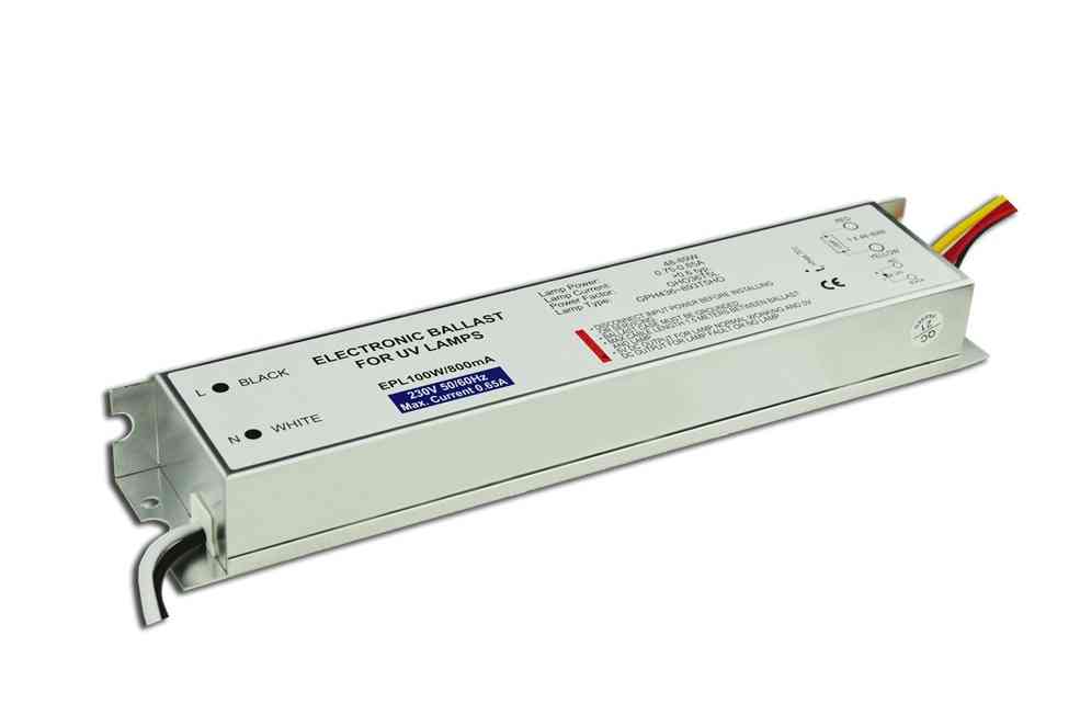
1. Instant Start UV Ballast
- Key Features:
- Instantly lights up UV lamps without preheating the filament.
- Ideal for environments where frequent startups aren’t needed.
- Suitable for budgets where cost is a concern.
- Best for applications with less than 4 on/off cycles per day.
- Typically paired with standard output UV lamps for air sterilization.
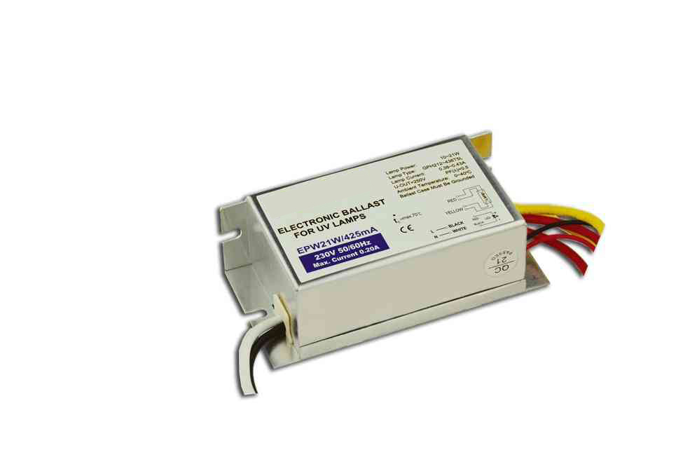
2. Rapid Start UV Ballast
- Key Features:
- Similar to Instant Start it provides a slightly smoother startup process.
- Also best for environments with minimal startup needs and budget constraints.
- Suitable for air sterilization applications with less than 4 on/off cycles per day.
3. Preheat Start UV Ballast
- Key Features:
- Designed for frequent on/off switching and low-temperature environments.
- Offers high lifespan and reliability.
- Ideal for use with mercury or high-output UV lamps.
- Commonly used in water treatment systems.
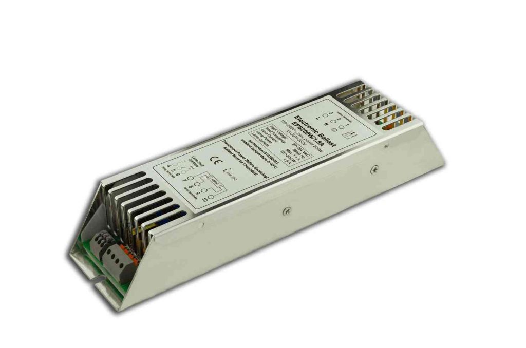
Choosing the right ballast type ensures your UV system operates efficiently and meets the specific needs of your application.
Why Your UV Ballast Might Not Be Working (And How to Fix It)
Sometimes your UV ballast might not turn on the UV lamps or fail to work properly. Let’s explore some common issues and their solutions:
1. Is the UV Lamp Not Bright Enough or Turning Red?
Possible Causes:
The lamp might not match the ballast.
The working temperature could be too low, causing the lamp power to be insufficient and making the lamp turn red.
Solution:
Ensure the lamp is compatible with the ballast.
Check and adjust the temperature to ensure it’s not too low.
2. Is the UV Lamp Turning Black?
Possible Causes:
Incorrect input voltage.
Frequent on/off cycles.
High starting voltage or incorrect preheat time.
The preheat current of the ballast might be too high.
Solution:
Make sure the lamp matches the ballast.
Avoid turning the lamp on and off too often.
For frequent use (more than 4 times a day), use our preheat start models. If less frequent (less than 4 times a day), choose our instant start models.
3. Is the Surface Temperature of the UV Ballast High?
Possible Causes:
It’s normal for ballasts to heat up, but they should stay below 70°C.
Solution:
If the ballast feels too hot, consider using air cooling to lower the temperature.
4. Does the UV Ballast Have Power but the UV Lamp Won’t Turn On?
Possible Causes:
The lamp might not be compatible with the ballast.
Incorrect connection between the lamp and the ballast.
Solution:
Check the datasheet to ensure compatibility and verify all connections.
5. Is the Ballast Completely Unresponsive?
Possible Causes:
No power supply to the ballast.
Voltage inconsistency with the ballast.
Incorrect power line connections.
Solution:
Ensure the power supply is active, the voltage matches the ballast requirements, and the power lines are connected correctly.
These tips should help you troubleshoot and resolve common UV ballast issues, ensuring your UV system runs smoothly!
UV Ballast Types: Inductive UV Ballast vs Electronic UV Ballast
UV ballasts come in two main types: Inductive and Electronic.
Inductive Ballasts rely on electromagnetic induction to power UV lamps. They have a steel core wrapped with copper wire windings. These ballasts are more affordable but tend to be less efficient compared to their electronic counterparts.
Electronic Ballasts use advanced solid-state electronic circuitry with high-frequency switching to ignite and power UV lamps. They offer better energy efficiency and more precise control than inductive ballasts.
Choosing the right UV ballast depends on the type, wattage, and number of UV lamps in your disinfection system. The ballast is crucial for transforming your facility’s voltage and current into the exact electrical conditions needed to properly power the UV lamps and ensure effective disinfection.
How to Test a UV Ballast: A Simple Step-by-Step Guide
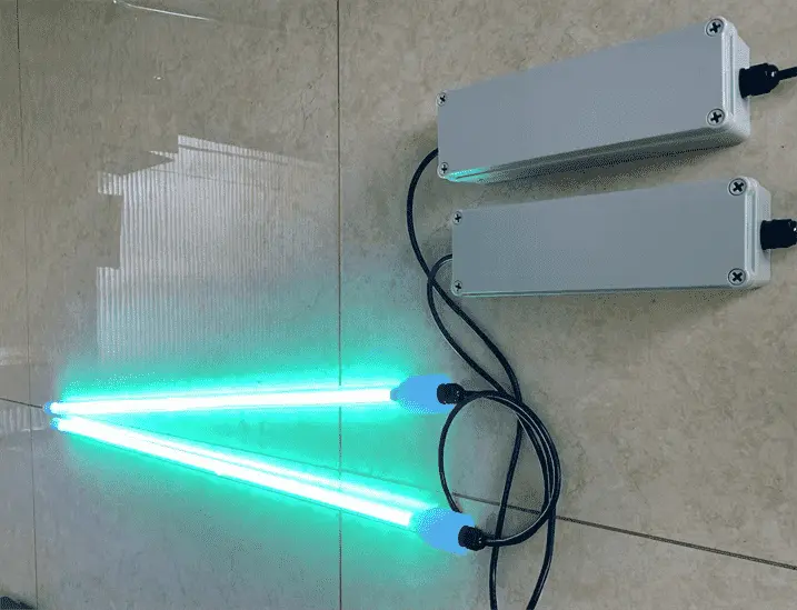
- Visual Inspection: Start by checking the ballast, UV lamps, and electrical connections. Look for any signs of damage, corrosion, or leaks. Make sure the lamps are clean and free of dust, and confirm that all connections are secure.
- Test Lamp Ignition: Turn on the power and see if the lamps ignite and stay lit. If you notice flickering, a delayed start, or if the lamps don’t light up at all, there may be an issue with the ballast.
- Measure Lamp Voltage: Use a voltmeter to check the voltage of the lamps. For a typical low-pressure UV lamp, the voltage should be around 40-60 VAC once the lamp has warmed up.
- Check Power Supply: Ensure the input voltage to the ballast is within the correct range (for example, 108VAC to 132VAC for a 120V ballast). Also, look out for signs of overheating or charring on electrical connections.
Understanding UV Ballast Output Voltage: Key Information You Need
Content:
A UV ballast is crucial for controlling UV lamps. It converts AC mains power into stable DC power, managing both voltage and current for the lamp. Typically, UV electronic ballasts output voltages ranging from 200V to 1000V. Initially, a high voltage is used to ignite the lamp, and once it’s lit, the ballast reduces the voltage to maintain steady illumination.
How Does a UV Ballast Work?
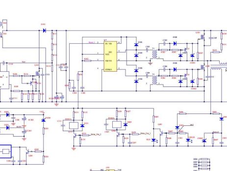
Understanding how a UV ballast works is key to ensuring your UV lamps operate efficiently and effectively. A UV ballast is the core component of any UV lamp system, converting unstable power into the stable current needed to power UV lamps. Here’s a breakdown of how a UV ballast works and the key processes involved.
1. Power Conversion
The process starts with power filtering to stabilize and clean the input current from the mains. The ballast converts alternating current (AC) from your power source into direct current (DC) using a transformer. This step adjusts the voltage up or down to match the UV lamp’s requirements.
2. Rectification
Once the voltage is adjusted, the rectification process kicks in. A rectifier bridge converts The AC power into DC power, ensuring that the UV lamp receives a consistent and stable current.
3. Filtering
After rectification, the DC might still contain some noise or ripple. The ballast uses capacitors to filter out these imperfections, resulting in a smooth and stable DC output.
4. Voltage Regulation
The ballast then regulates the voltage to ensure it stays within a certain range, matching the UV lamp’s operating needs. This regulation is crucial for the lamp’s stability and longevity.
5. Oscillation and High-Frequency Pulses
To turn on the UV lamp, the ballast uses a process called oscillation. This involves creating high-frequency pulses through the interaction of capacitance and inductance within the ballast. When these frequencies resonate, they generate a high starting voltage, which is necessary to ignite the UV lamp.
6. Lamp Operation
Once the lamp is turned on, the ballast continues to provide a normal current to maintain its operation. The ballast’s job is to ensure the UV lamp runs smoothly by controlling the current and keeping the power stable.
Through these stages—power conversion, rectification, filtering, voltage regulation, and oscillation—the UV ballast transforms unstable power input into a stable DC, enabling your UV lamp to function reliably.
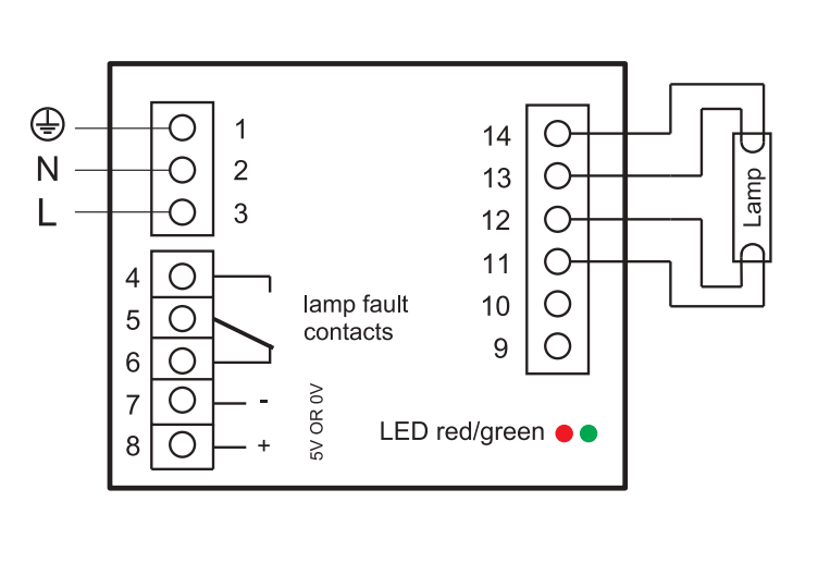
For a visual representation of how a UV ballast works, check out the image on this link.
What is a UV Electronic Ballast?
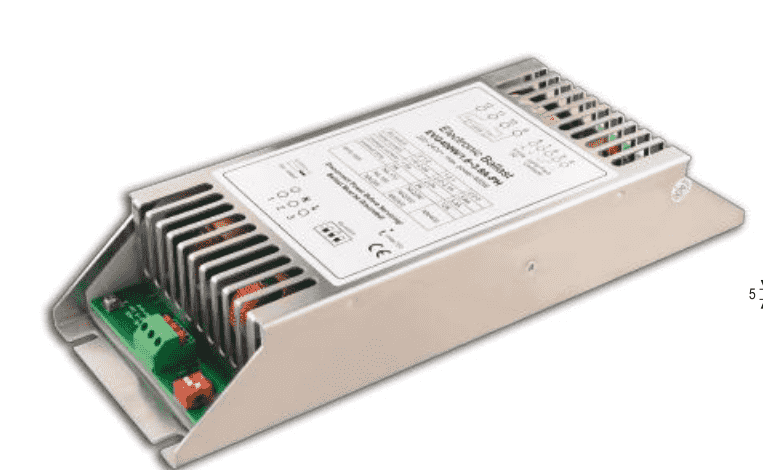
A UV electronic ballast is a key component used to power ultraviolet (UV) lamps. It manages the electrical conditions needed to start and run these lamps effectively. Here’s how it works: the ballast provides a high initial voltage to ignite the UV lamp, then adjusts the voltage and controls the current to keep the lamp running smoothly. This regulation ensures that the UV lamp operates efficiently and reliably, making it essential for applications like disinfection and various industrial processes.
How to Replace a UV Ballast: Step-by-Step Guide
Content:
Replacing a UV ballast is straightforward if you follow the right steps:
1. Turn Off the Power: Start by switching off the power to the UV system at the breaker box. This ensures safety while working on the electrical components.
2. Access the Ballast: Open the electrical cabinet where the ballast is housed. Locate the wiring connected to the ballast.
3. Disconnect the Wiring: Carefully disconnect the wires from the old ballast. Take note of the wire colors and their connections, as this will help when installing the new ballast. Once the wiring is disconnected, remove the ballast from its mounting.
4. Install the New Ballast: Follow the manufacturer’s instructions to mount the new ballast and reconnect the wires. Make sure you match the wiring configurations exactly as they were with the old ballast.
5. Restore Power and Test: After installation, turn the power back on and test the UV system. Switch on the lamps and use a UV meter to check that the intensity levels are within the required specifications. Also, check for any errors or faults in the system.
6. Fine-tuning: The new ballast may need some minor adjustments to ensure optimal performance. Retest the system after these adjustments to confirm everything is working correctly.
By following these steps, you can safely replace your UV ballast and ensure your UV system continues to operate effectively. Regular maintenance and proper installation help extend the lifespan of your new ballast, keeping your system running smoothly.
What is a UV Sensor? How They Work and Why They Matter
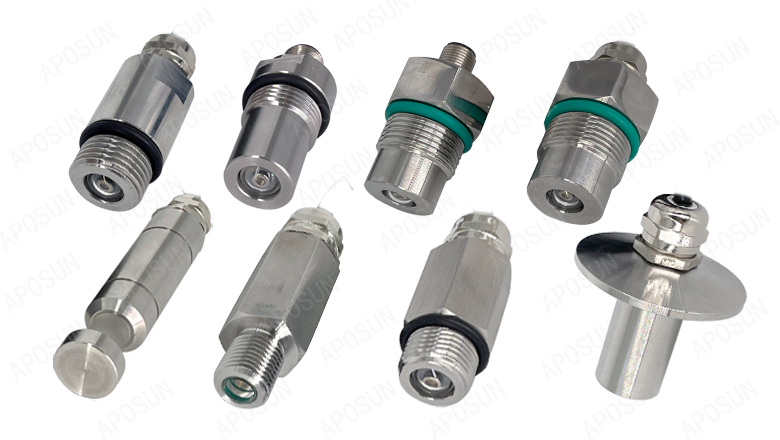
What is a UV Sensor?
A UV sensor is a device that detects ultraviolet (UV) radiation, which is invisible to the human eye. These sensors measure the intensity of UV rays from both natural and artificial sources, making them essential in various applications, including healthcare, industrial processing, and environmental monitoring.
UV rays, which have shorter wavelengths and higher energy than visible light, can be beneficial in small amounts but harmful in excess. UV sensors help monitor and detect these invisible UV emissions, ensuring safety and optimal performance across different environments.
Types of UV Sensors
UV sensors come in various types, each based on different detection principles. The most common types include semiconductor, photodiode, and photochemical sensors. These sensors convert UV radiation into an electrical signal proportional to the intensity of the UV light. For instance, at APOSUN, we use semiconductor UV sensors to provide accurate UVC intensity measurements.
How UV Sensors Work
UV sensors detect ultraviolet light and convert it into an electrical signal or numeric output. The key components of a UV sensor include:
– Photodetector: Detects incoming UV photons and generates an electrical current proportional to the UV intensity. Materials like silicon carbide, aluminum nitride, and gallium nitride are commonly used.
– Filters: Optical filters limit the UV wavelength range that reaches the photodetector, allowing the sensor to measure specific UV bands (UVA, UVB, UVC).
– Amplifier Circuit: Amplifies the weak electrical signal from the photodetector into a stronger output voltage, with gains up to 1 million times.
– Analog/Digital Converter: Converts the amplified analog signal into a digital output for processing, assigning a numeric value corresponding to the measured UV intensity.
The photodetector works through the photoelectric effect, where UV photons excite electrons, generating an electric current. The sensor’s performance depends on the photodetector’s responsivity—its ability to convert UV photons into an electrical signal. Higher responsivity leads to better sensitivity and detection accuracy.
Types of UV Light Sensors
UV light sensors are made from different semiconductor materials, each with unique properties:
– Silicon Carbide (SiC): Detects UV light from 200-400 nm, covering UVB and most of the UVC spectrum. SiC sensors are robust and can operate at high temperatures, making them suitable for harsh environments.
– Gallium Nitride (GaN): Sensitive to 200-365 nm UV light, with high responsivity and gain. GaN sensors are known for their speed, radiation hardness, and chemical inertness.
Key Specifications of UV Sensors
When selecting a UV sensor, consider these key specifications:
– Spectral Response: The range of UV wavelengths a sensor can detect, with different sensors designed for UVA, UVB, or UVC detection.
– Dynamic Range: The range of UV intensity the sensor can measure, typically from 0.1 mW/cm² to 20 W/cm² or more.
– Response Time: How quickly the sensor reacts to changes in UV levels. Faster response times (under a second) are ideal for real-time monitoring.
How to Use UV Sensors
Proper installation, positioning, and maintenance are crucial for optimal UV sensor performance.
– Installation: Mount the sensor in a location with direct UV exposure, ensuring the photodiode faces upward. Protect the sensor from moisture and weathering.
– Positioning: Place the sensor above ground and away from surrounding objects to minimize scattering and absorption of UV rays. Keep the photodiode clean.
– Maintenance: Regularly inspect the sensor housing, validate sensor readings, and replace the UV photodiode every 2-3 years to maintain accuracy.
Advantages of UV Sensors
UV sensors are highly sensitive, durable, and cost-effective, making them ideal for various applications:
– High Sensitivity: Designed to detect even low levels of UV rays with great responsiveness.
– Durability: Built to withstand harsh conditions, UV sensors are made from rugged materials like silicon carbide and gallium nitride.
– Cost-Effectiveness: UV sensors offer excellent value for their performance, with advancements making them more affordable.
Limitations of UV Sensors
While UV sensors are powerful tools, they do have some limitations:
– Spectral Range: UV sensors detect specific UV wavelengths and may not cover the full UV spectrum (100-400 nm).
– Temperature Dependence: UV sensor readings can vary with temperature, requiring compensation for consistent accuracy.
By understanding these aspects, you can choose the right UV sensor for your application and ensure it operates effectively over time.
How to Choose the Best UV Ballast for Your UV System: Complete Guide
UV ballasts are essential for ensuring your UV lamps operate under optimal conditions, maximizing performance and extending their lifespan. This guide will walk you through the key factors to consider when selecting the right UV ballast for your disinfection, curing, or analytical applications. We’ll cover everything from lifespan and sizing to compatibility and how to identify the perfect ballast for your system. With the right UV ballast, you’ll get the most out of your lamps in terms of performance, longevity, and return on investment.
Fluorescent Ballasts vs. UV Ballasts: Why You Shouldn’t Mix Them
You might wonder: can I use a fluorescent ballast for a UV lamp? The short answer is no.
UV light systems require specialized ballasts designed to handle the unique demands of generating UV rays. While fluorescent and UV lamps might seem similar, their electrical requirements differ significantly. Using a fluorescent ballast in a UV system can result in poor performance, lamp damage, and other issues.
Here’s why:
– Different Output Specifications: Fluorescent ballasts are built to power phosphor-coated lamps, while UV ballasts provide the higher peak voltages needed for UV output.
– Electrical Components: UV ballasts are designed to withstand the higher voltages required by UV lamps, whereas fluorescent ballasts lack the necessary insulation and construction.
– Wavelength Calibration: Fluorescent ballasts are tuned for visible light, while UV ballasts are calibrated specifically for ultraviolet wavelengths (100-400 nm).
In summary, UV systems have unique requirements that demand dedicated UV ballasts. Using the wrong type will likely damage your UV lamps and reduce system reliability.
UV Ballast Lifespan: What to Expect
A long-lasting UV ballast is crucial for minimizing maintenance and replacement costs. Higher-quality ballasts, often made by reputable brands, can last up to 20,000 hours with proper care, although they come with a higher upfront cost.
Factors affecting ballast lifespan include:
– Quality of Manufacturing: Ballasts made with durable components tend to last longer.
– Operating Temperature: Ballasts work best at temperatures between -20°C and 40°C. Excessive heat can degrade components and shorten the ballast’s life.
– On/Off Cycles: Frequent power cycling causes wear and tear, stressing components over time.
– Maintenance: Regular inspections, cleaning, and checking connections can extend ballast life. Keeping a log of operating hours helps you anticipate when a replacement is needed.
The Importance of Matching Ballasts and Lamps
Properly matching your UV ballast to the specific parameters of your lamps is crucial for system performance.
Key matching factors:
– Quantity: Make sure your ballast is designed to power the correct number of lamps.
– Startup Type: Match the startup method of the ballast with the lamp type. For example, preheat start ballasts should be used with 4-pin UV lamps, while instant start ballasts work with 2-pin UV lamps.
– Power and Current: Ensure the ballast’s power, current, and other parameters match those of the UV lamps.
Mismatching ballasts and lamps can lead to problems like overloading the ballast, underpowering the lamps, and wasting electricity. Always refer to the ballast’s nameplate for its specifications and ensure it’s a perfect match for your UV system.
Determining the Right Ballast Size
Choosing the right ballast size for your UV system is essential for optimal performance. Here are the factors you need to consider:
– UV Lamp Power Requirements: The number and wattage of your UV lamps will determine the ballast size you need. Higher-wattage systems with multiple lamps require larger ballasts.
– Distance from Ballast to Lamp: Longer distances require higher voltage to compensate for voltage drop. A larger ballast size may be necessary if your UV lamps are far from the ballast.
– Lamp Type: Different types of UV lamps have varying voltage and current requirements. For example, medium-pressure lamps typically need larger ballasts.
– Number of Lamps: If you’re using a single ballast for multiple lamps, make sure it’s large enough to power all of them.
– Future Expansion: Consider potential future needs. Choosing a ballast that can handle additional lamps allows for scalability.
Properly sizing your ballast ensures safe, efficient, and reliable operation over the long term. Always consult UV experts and manufacturer guidelines when making your selection.
Ballast Impact on Lamp Life
The type of ballast you use can significantly affect the lifespan of your UV lamps.
Here’s how:
– Electronic Ballasts: These operate at high frequency, eliminating flicker and reducing wear on the lamp cathodes, which extends lamp life.
– Magnetic Ballasts: These operate at 60Hz, which can cause flickering and uneven power output, leading to quicker wear and shorter lamp life.
Switching from magnetic to electronic ballasts is one of the easiest ways to prolong your UV lamps’ life. The steadier power delivery allows for thousands of additional hours of operation before replacement is necessary.
Identifying the Correct Ballast for Your UV Lamp
Using the right ballast for your specific UV lamp type is crucial for proper operation. UV lamps need specially designed ballasts to provide the correct starting voltage and operating current. Using an incompatible ballast can result in lamps that fail to start or have a shortened lifespan.
Common UV lamp types and their ballast requirements:
– Low-Pressure UV Lamps: Require a ballast matched to their specific wattage. Never use a medium-pressure ballast with low-pressure lamps.
– Medium Pressure UV Lamps: Need a medium-pressure ballast due to their higher wattage requirements.
– Amalgam UV Lamps: These contain mercury amalgam and need a ballast capable of providing higher starting voltages.
Always check the lamp manufacturer’s specifications and consult with UV system designers or ballast manufacturers to ensure compatibility. Mismatching can lead to unsafe operating conditions and reduced system performance.
Low-Pressure vs. Medium-Pressure UV Lamps: Key Differences Explained
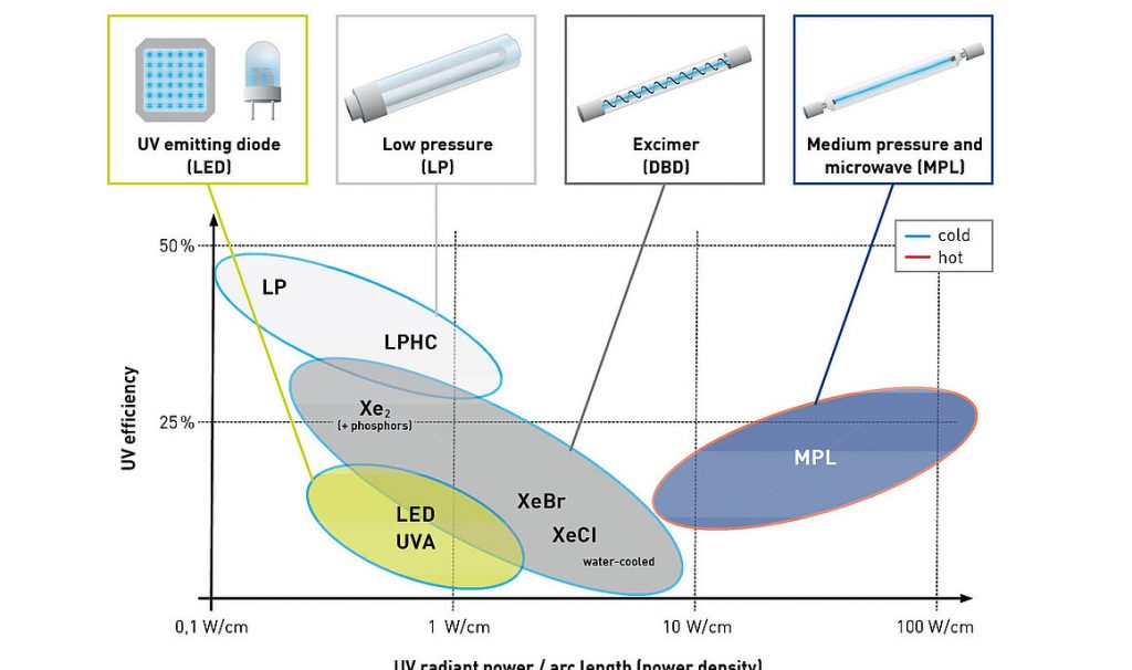
Low-pressure and medium-pressure UV lamps differ in several key aspects, including wavelength, effectiveness, structure, lifespan, disinfection speed, and safety.
Wavelength and Definition:
Medium-Pressure UV Lamps: Operate in a wavelength range of 200-400nm.
Low-Pressure UV Lamps: Operate in a narrower wavelength range of 100-280nm.
Effectiveness:
Low-Pressure UV Lamps: Primarily used to kill bacteria, viruses, and other microorganisms in the air, making the air cleaner.
Medium-Pressure UV Lamps: Commonly used for disinfecting water, making them ideal for water treatment applications.
Structure:
Medium-Pressure UV Lamps: Utilize xenon gas to produce ultraviolet light.
Low-Pressure UV Lamps: Use mercury, either in liquid or vapor form, to generate UV light.
Lifespan:
Medium-pressure UV Lamps: Generally have a longer lifespan compared to low-pressure UV lamps.
Disinfection Speed:
Medium-Pressure UV Lamps: Disinfect faster than low-pressure UV lamps.
Safety:
Medium-pressure UV Lamps: Often come with built-in safety features that automatically detect UV intensity, reducing the risk of UV leakage and making them safer to use.
Application Areas:
Medium-Pressure UV Lamps: Best suited for swimming pools, sewage treatment, and other water treatment applications.
Low-Pressure UV Lamps: Widely used in air purification, surface disinfection, and drinking water treatment.
Conclusion:
The choice between medium-pressure and low-pressure UV lamps should depend on your specific needs and the environment in which they’ll be used, as they differ in wavelength, effectiveness, structure, lifespan, disinfection speed, and safety.
Top 10 UV Lamp Manufacturers and Suppliers Worldwide
Are you looking to pair your UV systems with reliable UV lamps? This guide will introduce you to the top UV lamp manufacturers and suppliers around the globe, helping you find the perfect partner for your specific needs.
Why UV Lamps Matter:
In recent years, the demand for UV lamps has surged due to their vital role in sterilization, water purification, air disinfection, and various industrial applications. These lamps emit ultraviolet radiation, making them essential for effective sanitization in healthcare facilities, manufacturing plants, laboratories, and public spaces.
Market Overview:
The UV lamp market is thriving, with a value of $402.4 million in 2023, expected to soar to $1,220.4 million by 2033, growing at a CAGR of 14.9%. This growth is driven by the rising need for strict hygiene standards, especially in light of global health challenges.
APOSUN Advantage:
APOSUN’s UV monitors and sensors are compatible with a wide range of UV lamp brands and models. They’re designed to easily track your UV lamp’s performance by matching its unique power, current, and other key settings. This ensures real-time data that helps you make smart decisions.
Top 10 UV Lamp Manufacturers and Suppliers:
1. Heraeus Noblelight

Global leaders in specialty light sources, from ultraviolet to infrared, serving industrial, scientific, and medical sectors.
2.LightSources and LightTech

With 40 years in the UVC germicidal lamp industry, these companies provide innovative disinfection solutions.
3. Philips Lighting

Experts in UV-C technology, offering cutting-edge solutions for equipment manufacturers and purification companies.
4. Ushio Inc.

Based in Tokyo and established in 1964, Ushio specializes in UV and visible light technologies.
5. American Ultraviolet

Custom UV lamp manufacturers provide solutions for HVAC systems and beyond.
6. First Light Technologies
Leading manufacturers of low and medium-pressure UVC lamps, crucial for water and air disinfection.
7. Atlantic Ultraviolet Corporation

Renowned producer of germicidal UV lamps and water purification systems.
8.UltraViolet Devices

Innovators in UV disinfection since 1949, focused on public health protection.
9. Light Spectrum Enterprise

Specialists in UVC lighting since 2007, offering solutions for OEMs worldwide.
10. Arklite

India’s only quartz-based UV lamp manufacturer, providing a range of low-pressure UV lamps for disinfection.
A typical UV water disinfection system comprises essential components, including a UV reactor chamber, control panel, UV monitoring system, and automatic wiper system. The UV reactor chamber, constructed from robust stainless steel, holds and disinfects water using UV-C lamps. The chamber’s design, with integrated baffles and flow diverters, ensures optimal water flow for effective UV exposure.
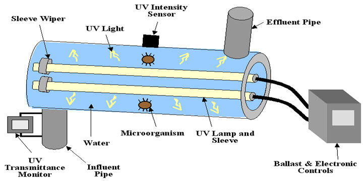
Control Panel and Monitoring System:The control panel serves as the central hub in the UV water disinfection system, facilitating monitoring and control.
System Monitoring: Displays UV intensity, dose, flow rate, and operating temperature for operators to assess system performance.
UV Intensity Monitoring: Utilizes UV sensors to measure real-time intensity, crucial for ensuring sufficient UV dose for effective disinfection.
Lamp Life Tracking: Monitors operating hours of UV lamps, alerting operators when replacement is needed.
System Control: Allows system activation, adjustment of UV dose rate, and other functions, with some systems offering automatic adjustments for optimal performance.
Alarm System: Alerts operators to issues such as reduced UV dose, lamp failure, or abnormal flow rate, preventing ineffective disinfection.
Data Logging: Some control panels log performance data (e.g., UV intensity and flow rate) over time, aiding in record-keeping, performance tracking, and issue identification.
UV Monitoring System: This system verifies the administered UV dose, ensuring the accurate delivery of the required dose for effective disinfection.
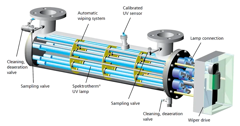
Automatic Wiper System: The automatic wiper system is crucial for maintaining optimal UV performance. It cleans quartz tubes housing UV lamps to prevent surface coating with scale, biofilm, or other substances present in water or wastewater. This coating can reduce UV light passage, leading to decreased UV dose and disinfection effectiveness. The automatic wiper system periodically wipes UV lamp surfaces, ensuring a consistently sufficient UV dose.
The necessity of an automatic wiper system depends on water quality. In instances of high hardness, turbidity, or substances that may coat lamps, an automatic wiper system proves particularly beneficial. Conversely, in relatively clean water, the need for an automatic wiper system may be less pronounced. The comprehensive integration of these components ensures the UV water disinfection system’s effectiveness and reliability in various water treatment scenarios.
Choosing a suitable UV sensor for a water system involves considering various factors to ensure it meets the specific needs of your application. Here are key considerations when selecting a UV sensor for a water system:
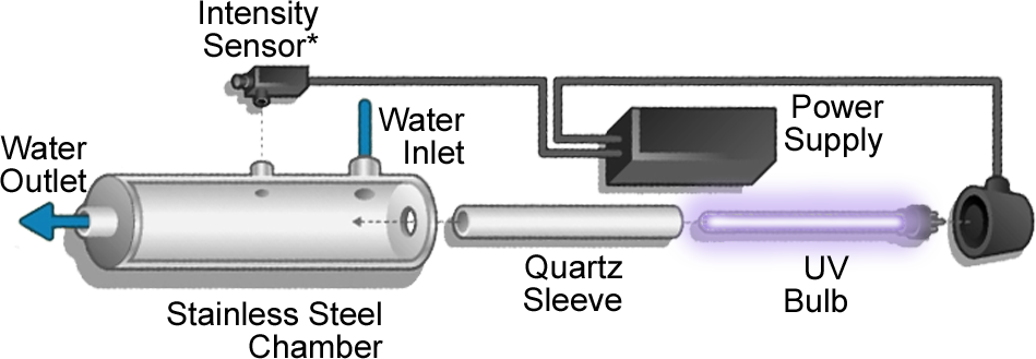
Type of UV Radiation:
Identify the type of UV radiation relevant to your water system. Determine whether UVA, UVB, or UVC sensors are required based on the UV lamps or sources used for disinfection.
Wavelength Range:
Choose a UV sensor with a wavelength range that matches the UV lamps in your water treatment system. Different UV sensors are designed for specific wavelength bands, so ensure compatibility.
Application Purpose:
Consider the purpose of UV measurement in your water system. For disinfection purposes, a sensor focused on germicidal wavelengths (e.g., UVC) may be suitable, while other applications might require a broader spectrum.
Measurement Range:
Select a UV sensor with an appropriate measurement range to cover the intensity levels expected in your water treatment system. Ensure that the sensor can accurately measure the range of UV intensities relevant to your application.
Accuracy and Precision:
Look for a UV sensor with high accuracy and precision. Accurate measurements are crucial for ensuring effective disinfection and compliance with regulatory standards.
Response Time:
Consider the response time of the UV sensor. Faster response times are important in dynamic systems where rapid changes in UV intensity require immediate monitoring and adjustments.
Environmental Conditions:
Assess the environmental conditions in which the UV sensor will operate. Ensure that the sensor is designed to withstand factors such as temperature, humidity, and exposure to chemicals commonly found in water treatment environments.
Sensor Type:
Choose between different types of UV sensors, such as screw type,(NPT, UNC, UNF, G…), screw size(1/2,1/4,3/4…), photodiode sensors, photomultiplier tube (PMT) sensors, or other technologies. Consider factors like sensitivity, stability, and the sensor’s ability to perform well in your specific application.
Integration:
Ensure that the UV sensor can be easily integrated into your water treatment system. Check for compatibility with communication protocols used in your system for seamless integration.
Calibration and Maintenance:
Consider the ease of calibration and maintenance. Choose a UV sensor that facilitates straightforward calibration processes and provides alerts or reminders for routine maintenance.
Output and Compatibility:
Verify the output signal type (RS485, RJ45, analog, digital, etc.) and compatibility with monitoring or control systems in your water treatment setup.
Certifications and Standards:
Verify that the UV sensor complies with relevant industry standards and certifications. This ensures that the sensor meets quality and performance requirements.
Cost Consideration:
Consider your budget while ensuring that the selected UV sensor meets the necessary requirements for your specific application.
Manufacturer Reputation:
Choose a UV sensor from a reputable manufacturer with a history of producing reliable and high-quality sensors.
By carefully evaluating these factors, you can choose a UV sensor that is well-suited to your water system’s requirements, contributing to effective UV monitoring and disinfection processes.
Choosing a suitable online UV intensity monitor for a water system involves considering various factors to ensure accurate and reliable measurements for effective disinfection. Here are key considerations when selecting an online UV intensity monitor:
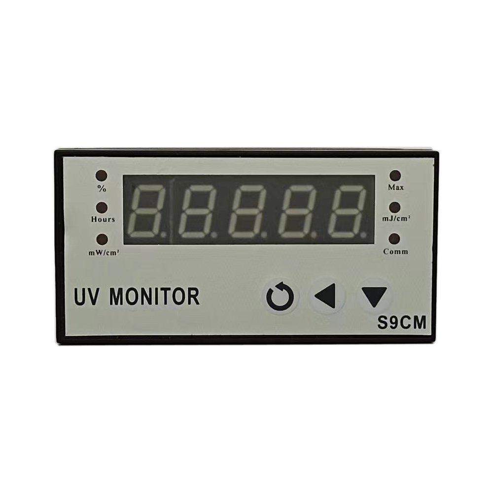
UV Lamp Type:
Identify the type of UV lamps used in your water treatment system (e.g., low-pressure or medium-pressure lamps). Ensure that the UV intensity monitor is compatible with the specific wavelength spectrum emitted by the lamps.
Wavelength Range:
Choose a UV intensity monitor with a wavelength range that corresponds to the UV lamps in use. For example, if the system uses low-pressure UV lamps emitting primarily in the UVC range (around 254 nm), the monitor should be suitable for measuring UVC wavelengths.
Measurement Range:
Consider the expected range of UV intensities in your water system. Select a monitor with a measurement range that covers the intensities relevant to your application. This ensures accurate readings across different operating conditions. APOSUN standard UV intensity monitor range is 0~20000uw/cm², other range can be customized.
Accuracy and Precision:
Look for a UV intensity monitor with high accuracy and precision to provide reliable measurements. Consider the sensor’s sensitivity to changes in UV intensity, especially in applications where rapid adjustments may be necessary. APOSUN standard UV intensity monitor accuracy is 0.1%,0.01% high accuracy is optional.
Response Time:
Choose a monitor with a response time suitable for your application. Faster response times are crucial for systems with dynamic UV intensity changes, allowing for real-time adjustments and ensuring effective disinfection.
Environmental Conditions:
Assess the environmental conditions in which the UV intensity monitor will operate. Ensure that the monitor is designed to withstand factors such as temperature, humidity, and exposure to chemicals commonly found in water treatment environments.
Integration and Compatibility:
Ensure that the UV intensity monitor is compatible with the control and monitoring systems in your water treatment setup. Check for compatibility with communication protocols used in your system for seamless integration.
Calibration and Maintenance:
Consider the ease of calibration and maintenance. Choose a UV intensity monitor that facilitates straightforward calibration processes and provides alerts or reminders for routine maintenance.
Alarm Systems:
Opt for a monitor with alarm systems that can trigger alerts or notifications if UV intensity falls outside the specified range. This feature enables prompt corrective actions. APOSUN UV intensity monitor has a relay alarm for both UV relative intensity and UV lamp life.
Data Logging and Analysis:
Evaluate the data logging and analysis capabilities of the UV intensity monitor. Some monitors offer features for storing historical data, which can be valuable for performance assessments and regulatory compliance. APOSUN CHS9CM has RS485,4-20MA,1-5V analog output for data logging and Analysis.
By carefully considering these factors, you can select a suitable online UV intensity monitor that aligns with the specific requirements of your water system, contributing to the effectiveness of UV disinfection processes.
Should we pay attention to the UV light pressure when we choose a suitable UV intensity sensor?
Yes, we must!!
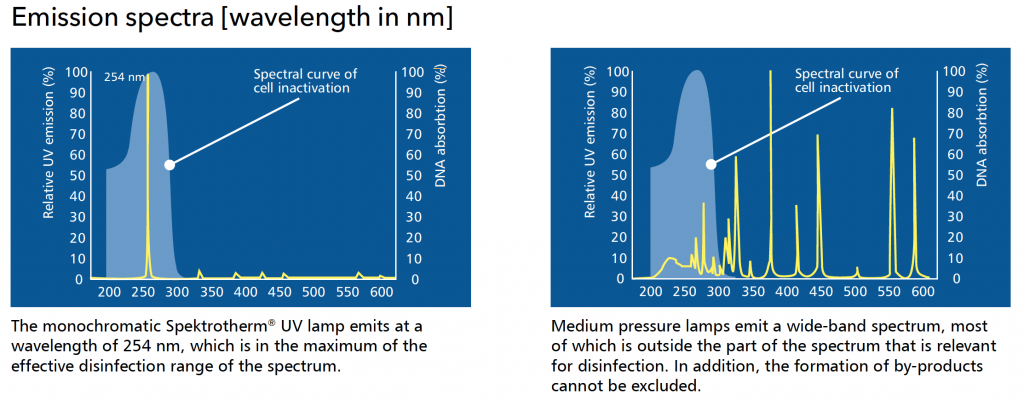
Low-pressure (LP) UV lamps and medium-pressure (MP) UV lamps are two different types of ultraviolet (UV) lamps commonly used in water treatment systems for disinfection purposes. The main differences between them lie in their design, wavelength spectrum, and applications. Understanding these differences is important when selecting a suitable UV intensity sensor for a particular UV lamp type. Here’s a breakdown of their distinctions:
Design:
Low-Pressure UV Lamps (LP): LP UV lamps are characterized by their long, slender shape. They operate at a low pressure and typically emit a monochromatic UV light at a specific wavelength, usually around 254 nanometers (UVC range).
Medium-Pressure UV Lamps (MP): MP UV lamps have a thicker, more robust design. They operate at higher pressures and emit UV light across a broader spectrum, including UVA, UVB, and UVC wavelengths.
Wavelength Spectrum:
Low-Pressure UV Lamps (LP): LP lamps primarily emit UV light at a specific wavelength, typically around 254 nm (UVC). This wavelength is effective for germicidal applications.
Medium-Pressure UV Lamps (MP): MP lamps emit UV light across a wider spectrum, including UVA, UVB, and UVC. While they still provide germicidal effects, they also have applications in processes where a broader UV spectrum is beneficial, such as advanced oxidation.
Applications:
Low-Pressure UV Lamps (LP): LP lamps are commonly used in water disinfection applications where the primary goal is to inactivate microorganisms, such as bacteria and viruses.
Medium-Pressure UV Lamps (MP): MP lamps find applications beyond disinfection. Their broader spectrum makes them suitable for processes requiring advanced oxidation, where organic and inorganic contaminants are targeted.
When choosing a suitable UV intensity sensor, it’s crucial to consider the type of UV lamp used in the water treatment system:
For Low-Pressure UV Systems:
A UV intensity sensor is designed to measure a broader spectrum of 210~375nm for Low-Pressure UV Systems because of the wavelength emitted by low-pressure UV lamps (around 210~280 nm only UVC).
For Medium-Pressure UV Systems:
A UV intensity sensor is designed to measure a narrower spectrum of UV wavelengths (Only UVC 210~280nm) for medium-pressure UV systems. A medium-pressure ultraviolet lamp not only emits UVC (ultraviolet C) but also generates UVB (ultraviolet B) and UVA (ultraviolet A) as byproducts.
It’s essential to match the characteristics of the UV intensity sensor with the specific UV lamp technology employed in the water treatment system to ensure accurate and reliable monitoring. Using the wrong type of sensor may result in inaccurate readings and compromise the effectiveness of the UV disinfection or treatment process.

A UV intensity sensor is a sensor designed to measure the intensity of ultraviolet (UV) radiation in water. These sensors are commonly used in water treatment applications, where UV radiation is employed for disinfection purposes to inactivate microorganisms. UV intensity sensors play a crucial role in ensuring that the UV disinfection process is operating at the desired levels of intensity to effectively treat and purify the water.
Here are the key features and functions of UV intensity sensors for water systems:
Measurement of UV Intensity:
UV intensity sensors measure the power per unit area of UV radiation in the water. The intensity is typically expressed in units such as watts per square meter (W/m²).
Wavelength Specific:
UV intensity sensors are designed to measure specific wavelengths of UV radiation. The wavelength range is chosen based on the characteristics of the UV lamps or sources used in the water treatment system.
Real-Time Monitoring:
These sensors provide real-time monitoring capabilities, continuously measuring UV intensity as water flows through the treatment system.
Integration with UV Disinfection Systems:
UV intensity sensors are integrated into UV disinfection systems to ensure that the UV lamps are emitting the required intensity for effective disinfection.
Feedback Control:
UV intensity sensors are often part of feedback control systems that automatically adjust the power supplied to UV lamps based on real-time UV intensity measurements. This helps maintain consistent disinfection levels.
Alarm Systems:
UV intensity sensors may include alarm systems that trigger alerts or notifications if UV intensity falls outside the specified range. This allows for prompt corrective actions.
Verification of UV System Performance:
These sensors are crucial for verifying and validating the performance of UV disinfection systems, ensuring they meet regulatory requirements and effectively treat waterborne pathogens.
Compact Design:
UV intensity sensors are often designed to be compact and easily integrated into existing water treatment infrastructure.
Calibration and Maintenance:
Regular calibration and maintenance are essential for the accuracy and reliability of UV intensity sensors. Some sensors may include features to simplify calibration processes.
Multiple Channels:
In systems with multiple UV lamps or sources, UV intensity sensors may have multiple channels to monitor and display the intensity of each source individually.
The information provided by UV intensity sensors allows operators to make informed decisions about the efficiency and effectiveness of the UV disinfection process. By ensuring that the UV intensity is within the desired range, these sensors contribute to the overall quality and safety of treated water.
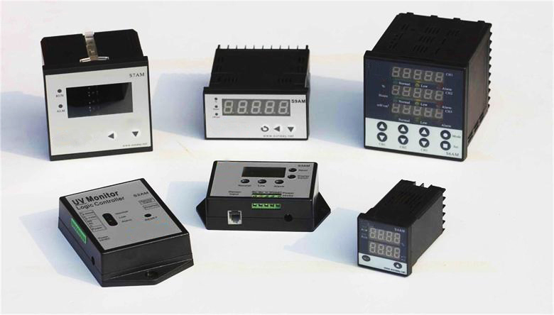
An online UV intensity monitor is a device designed to continuously measure and monitor ultraviolet (UV) radiation levels in real-time. These monitors are often used in various applications where UV radiation plays a crucial role, such as water treatment, air purification, and industrial processes. The term “online” signifies that the monitoring is performed continuously, providing immediate feedback on the UV intensity levels.
Here are key features and characteristics of online UV intensity monitors:
Real-time Monitoring:
Online UV intensity monitors provide instant and continuous measurements of UV radiation levels, allowing for prompt responses to any variations or deviations.
Application in Water Treatment:
In water treatment systems, online UV intensity monitors are used to ensure that UV disinfection processes are operating at the desired intensity levels for effective pathogen inactivation.
Air Purification:
In air purification systems, especially those using UV lamps to eliminate airborne contaminants, online UV intensity monitors help maintain optimal disinfection conditions.
Industrial Processes:
Online UV intensity monitoring is utilized in various industrial processes where UV radiation is employed for curing, drying, or sterilization. It ensures that UV levels are consistent for the desired outcomes.
Automation and Control:
These monitors are often integrated into control systems, allowing for automated adjustments based on the real-time UV intensity data. This helps maintain process efficiency and effectiveness.
Data Logging and Analysis:
Online UV intensity monitors may include features for data logging and analysis, allowing for historical tracking of UV levels and performance assessments over time.
Alarm Systems:
Many online UV intensity monitors are equipped with alarm systems that can trigger alerts or notifications if UV levels fall outside the specified range. This enables operators to take corrective actions promptly.
Remote Monitoring:
Some online UV intensity monitors offer remote monitoring capabilities, allowing users to access and view UV intensity data from a distance, enhancing convenience and accessibility.
Multi-Channel Monitoring:
In systems with multiple UV lamps or sources, online UV intensity monitors may have multiple channels to monitor and display the intensity of each source individually.
Calibration and Maintenance Features:
These monitors often include features for easy calibration and may provide alerts or reminders for routine maintenance.
By employing online UV intensity monitors, industries can ensure the effectiveness of UV-based processes, enhance system reliability, and comply with regulatory requirements. The continuous monitoring capability is particularly valuable in applications where maintaining consistent UV levels is critical for achieving the desired outcomes.
UVC (Ultraviolet-C) relative intensity value % and UVC absolute intensity value mw/cm² are metrics used to measure the strength or power of UVC radiation, a type of ultraviolet light with a wavelength range of approximately 200 to 280 nanometers. UVC radiation is often used for germicidal purposes, as it can effectively kill or inactivate microorganisms, including bacteria and viruses.
UVC Relative Intensity Value %:
The UVC relative intensity value % represents the percentage of UVC radiation emitted by a source relative to a reference source or a standard. This metric compares the output of different UVC devices, such as UVC lamps or UVC LEDs, to determine their relative effectiveness in germicidal applications. The higher the percentage, the more intense the UVC radiation emitted by the source. It helps in assessing the strength of the UVC source compared to a known benchmark.
UVC Absolute Intensity Value mw/cm² (milliwatts per square centimeter):
The UVC absolute intensity value mw/cm² represents the actual power or energy of UVC radiation that is delivered to a surface per unit area (usually per square centimeter). It measures the intensity of UVC radiation at a specific distance from the source and indicates how much germicidal power is available for disinfection. It is a more concrete and precise measurement of UVC irradiance.
In practice, to calculate the UVC absolute intensity value in milliwatts per square centimeter, you would typically need a UVC radiometer or a UVC sensor. These devices can measure the UVC irradiance at a given distance from the source and provide a value in mw/cm². This value is important for determining the effectiveness of UVC radiation in disinfection and sterilization applications, as it helps ensure that the desired dosage of UVC is delivered to the target surface to achieve the intended germicidal effect.
In summary, the UVC relative intensity value % is a comparative measure, while the UVC absolute intensity value mw/cm² is a specific measurement of UVC radiation power at a particular distance from the source. Both metrics are important in assessing and using UVC technology for germicidal purposes.
The UVC relative intensity value % and UVC absolute intensity value mw/cm² serve different purposes and provide different types of information, so the choice of which value to use depends on your specific needs and goals. Here’s a summary of the key differences and when to use each value:
UVC Relative Intensity Value %:
Comparative Measure: This value represents the percentage of UVC radiation emitted by a source relative to a reference source or a standard. It’s a relative measure used for comparing different UVC sources.
Use Cases: UVC relative intensity % is useful when you want to assess how one UVC source compares to another in terms of output strength. It’s helpful for benchmarking and determining the relative power of different UVC devices.
UVC Absolute Intensity Value mw/cm²:
Specific Measurement: This value represents the actual power or energy of UVC radiation delivered to a surface per unit area (typically per square centimeter). It provides a precise measurement of UVC irradiance at a specific distance from the source.
Use Cases: UVC absolute intensity in mw/cm² is essential when you need to know the exact power of UVC radiation at a particular location. It’s critical to ensure that the required UVC dosage is delivered for effective germicidal applications. For example, in disinfection or sterilization, it’s important to know the actual UVC intensity reaching a surface to achieve the desired level of microbial inactivation.
In practice, the choice between these values depends on your objectives:
If you want to compare different UVC sources or evaluate their relative strengths, use UVC relative intensity value %.
If you need to determine the actual UVC intensity at a specific location to ensure effective disinfection or sterilization, use the UVC absolute intensity value mw/cm².
For many practical applications, such as disinfecting surfaces in healthcare settings or water treatment systems, the UVC absolute intensity value mw/cm² is more critical, as it ensures that the appropriate germicidal dosage is delivered. However, the UVC relative intensity value % can still be useful for manufacturers or researchers when comparing and benchmarking different UVC devices or technologies.
UV intensity refers to the strength or amount of ultraviolet (UV) radiation present in a particular environment. UV radiation is a type of electromagnetic radiation with shorter wavelengths than visible light, and it is divided into three categories based on wavelength: UVA, UVB, and UVC.
UV intensity is typically measured in terms of power per unit area and is expressed in units such as watts per square meter (W/m²). The intensity of UV radiation can vary depending on factors such as the time of day, geographic location, altitude, atmospheric conditions, and the presence of reflective surfaces.
Exposure to high levels of UV radiation, especially UVB and UVC, can have harmful effects on living organisms, including humans. UV radiation is known to cause sunburn, premature aging of the skin, and an increased risk of skin cancer. It is important to protect oneself from excessive UV exposure by using sunscreen, wearing protective clothing, and avoiding prolonged exposure to direct sunlight.
1, What is IP Rating?
IP stands for International Protection Marking.
The first number shows how well it can resist dust;
The second number shows how well it can resist water flow;
The third number shows how well it can resist water flowing from any direction.
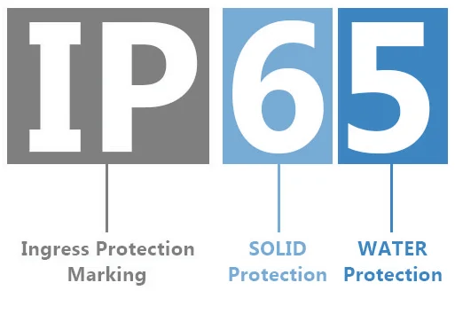
The following diagram will help you to understand the protection levels better corresponding to different values in IP rating.
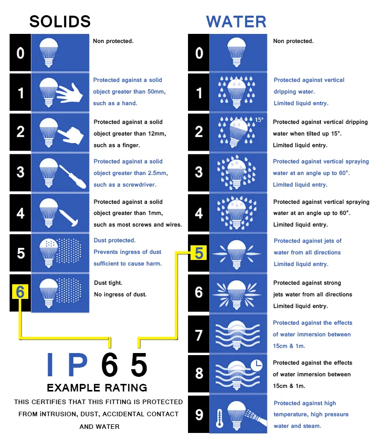
IP55 Waterproof
IP55: 5 represents good dust-proof and touch protection, and 5 represents good moisture-proofing.
Application: Suitable for dry or wet areas, such as the living room, kitchen, and bathroom. It’s not recommended to use it where water can be splashed.
IP65 Waterproof
IP65: 6 represents good dust-proof and touch protection. 5 stands for preventing spraying water from all directions.
Application: Suitable for wet or water-splashed areas for e.g. the kitchen, bathroom, and eaves. As the casing is hollow, it’s not recommended for outdoor use.
IP67 Waterproof
IP67: 6 represents good dust-proof and touch protection. 7 stands for underwater protection against water intrusion.
Application: can be immersed in water, such as a swimming pool, or fish tank.
How to set a digital panel meter for the displacement sensor?
The parameters of digital panel meters for displacement sensors generally include the upper limit of the measured value, the lower limit of the measured value, the upper limit of deviation, the lower limit of deviation, and the absolute value of the deviation. For example, the upper (lower) limit of the measured value is used to set the maximum (minimum) measuring range of the displacement. It is used to display the displacement value delivered to the DCS control system.
Ultraviolet (UV) light is found occupying the portion of the electromagnetic spectrum between X-rays and visible light. The sun emits ultraviolet light; however, much of it is absorbed by the earth’s ozone layer. Just as visible light consists of different colors that become apparent in a rainbow, the UV radiation spectrum is divided into three regions called UVA, UVB and UVC.
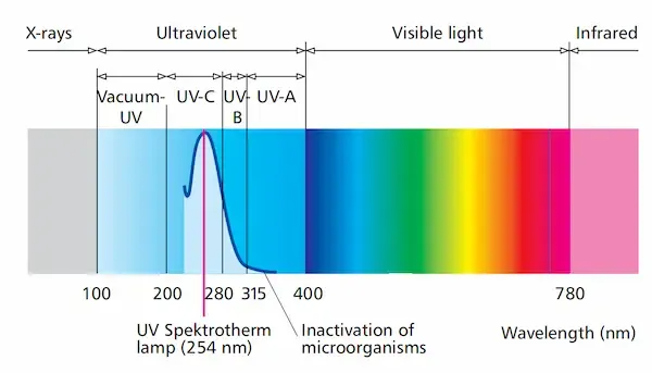
UV-A wavelength: 315-400 nm. Not absorbed by the ozone layer
UV-B wavelength: 280-310 nm. It is mostly absorbed by the ozone layer, but some do reach the Earth’s surface.
UV-C wavelength: 100-280 nm. It is completely absorbed by the ozone layer and atmosphere.
Short-wavelength UV-C is the most damaging type of UV radiation.
A unique characteristic of UV light is that a specific range of its wavelengths, those between 200 and 300 nanometers (billionths of a meter), are categorized as germicidal – meaning they are capable of inactivating microorganisms, such as bacteria, viruses and protozoa. This capability has allowed the widespread adoption of UV light as an environmentally friendly, chemical-free, and highly effective way to disinfect and safeguard water against harmful microorganisms.
Usage: Used in curing, aging, air sterilization, sewage treatment, water treatment, ozone detection, arc monitoring, and other industries.
There are 4 buttons on the panel of CHD9001,
I button, press to check the basic electrical parameters voltage, amp, power, reactive power, apparent power, power factor and frequency.
II button, press to check the power quality parameters(optional);
III button, press to check the KWH, KVah energy parameter;
AC 380V 5A or 380V 1A, others 220V 5A/1A
Sometimes the electric meter from the electric company reads CL 200 and 240 V.
That 240V means the meter box itself is designed for 240V electric service;
The CL200 means the box is rated for up to 200A continuous 220/240V power draw through it
It tells the power should not exceed 200A on each “side” or live lead of the 220/240V wiring, however can be less.
Aposun CHD9001 offers 2 types of measuring range for choice—3×220/380V 1A & 3×220/380V 5A. For the higher voltage or ampere, we can use relative Current transformer (CT) and Pressure transformer (PT).
Aposun CHD9001 3 phase LCD power engery meter measures up to 42 parameters. It’s a simple & reliable power energy monitor which is widely used in electric power systems, low-voltage distribution, environment monitor, etc..
| Line Voltage | UFab, UFbc, UFac | Total reactive power | TOT (KWH) | Date | DATE |
| Phase Voltage | Ua, Ub, Uc | Total inactive power | TOT(Kvarh) | Time | TIME |
| Current | Ia, Ib, Ic | Import reactive power | IMP (KWH) | ||
| Total/Phase reactive power | P, Pa, Pb, Pc (W) | Export reactive power | EXP (KWH) | ||
| Total/Phase inactive power | Q, Qa, Qb, Qc (Var) | Import inactive power | IMP(Kvarh) | ||
| Total/Phase apparent power | S, Sa, Sb, Sc | Export inactive power | EXP(Kvarh) | ||
| Total/Phase power factor | PF, PFa, PFb, PFc | Multi-rate total reactive power | F1, F2, F3, F4 (KWH) | ||
| Frequency | F | Multi-rate total inactive power | F1, F2, F3, F4 (Kvarh) |

